
PCB Teasers: 11/11/13
Two things this week - a 4-channel bidirectional mosfet level shifter (designed for 3.3V and 5V), and a MCP73831/2 test board. The level shifter is first, and the MCP73831/2 test board is after the jump. The level shifter took a while to lay out small enough for me to be satisfied. An explanation of how it works is coming.
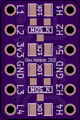
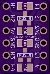
Now the MCP73831/2... that gave me grief in a design, so I made a board just for it.
The MCP73831/2 is a chip designed to charge lithium batteries (or, well, other types of batteries as well, I suppose, depending on your setup). The only difference between the 1 version and the 2 version is that the 1 has a tri-state status output (to source the current to drive an LED) and the 2 version has an open collector output (to sink the current through an LED).
Fairly simple, and the datasheet is here: MCP73831/2.
Two issues. First, thought the datasheet clearly shows that the 1 version has an open drain to sink current, that's not what it describes in words. Furthermore, two reference designs I found also disagree with what the datasheet shows. The datasheet shows it twice, in fact:
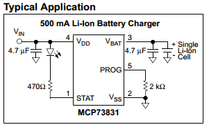
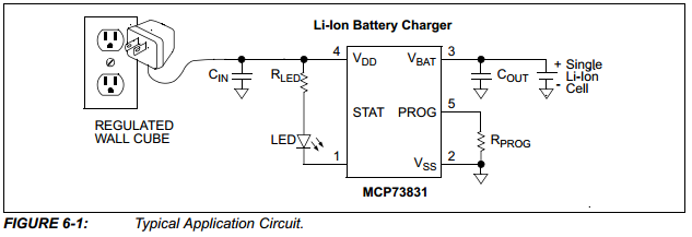


So I am not sure which is correct - the datasheet drawing, or the datasheet words and other peoples' schematics. That's issue number one.
Issue number two is that the bloody thing shorts out in the project where I used it. I have no idea why. I've gone over the schematic. I've gone over the board layout. I've gone over my solder joints. I simply have no clue why it shorts out. Why? My ideas are:
One, maybe it really needs the planes as it shows in the datasheet. Those were not absent in the design that shorts, I don't think, but neither were they precisely as described. I doubt this is the cause, but I've tried to replicate more precisely what they show.
Two, maybe I really do have a short somewhere, either in the schematic or in the layout.
Three, maybe trying to drive the LED is a problem. I don't imagine how. Even if I am wrong, and the datasheet is right, and the 1 version sinks, I can't see why it would short.
Four, the device should be nicely stable without the battery plugged in. Is it really? I don't know, but I'll try it both ways.
But frankly, there is only one solution: create an SSCCE: a short, self-contained, correct example. Which I have done here:
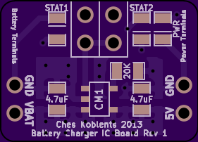
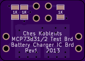
I've removed almost anything extraneous. I do have a power indicator LED. My status LEDs face both ways to allow either the 1 version or the 2 version to operate. In addition, I have jumpers to disconnect them entirely.
I hope this works. If not, I have no idea.
Ches Koblents
November 12, 2013
November 12, 2013