PIC SMD Tutorial Rev2 Analysis
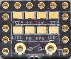
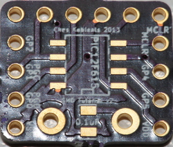
This is an update to my previous spin. I've fixed all of the issues! Version two has:
- PIC12F615 - 8 pin SOIC - or any other PIC with the same pinout
- Two 1k resistors - 1206
- Two LEDs - 1206
- Pushbutton, two pin - through hole
- Debounce capacitor - 0805
- Two 4-pin headers, one on each side, for the PIC breakout
- One 6-pin ICSP (in-circuit serial programmer) header for PIC programming
Here're the improvements I made, and some I'd like to make. In order of importance, improvements:
- Fixed headers to use 1mm drills. Otherwise, manufacturing variance may prevent proper header use!
- Fixed the ground plane issue.
- Tented vias with 12mil drills instead of 25mil drills.
- Fixed silkscreens for headers to be symmetrical.
- Fixed LED silkscreen to show polarity.
- Components no longer too close for inexperienced solderers.
- PIC moved to the bottom of the board, along with debounce capacitor.
- Kept 1206. Size is I/O bound, so no need to reduce size.
- Reduced board size to minimal rectangle as defined by the headers (so size is I/O bound).
So I fixed just about everything wrong with the first design. Some future changes are:
- Add signal names to top silkscreen (they are currently only on the bottom.)
- Change to a surface mount pushbutton.
- Validate other 8-pin PICs that have the same VSS/VDD/MCLR/PGD/PGC positions.
- Following that, use a PIC with UART and put LEDs on rx/tx.
However, it appears that I am pretty much done for now with the design. I'll probably make a third spin but it's not critical since things work perfectly as-is. The biggest weakness today is that the pinout has been flipped vertically from the datasheet; this can easily be remedied with proper documentation (which means people aren't referring to the datasheet pinout.)
Some relevant past work:
Pre-programming the PIC
Gerber renders (I'll post the real gerbers soon)
OSH Park renders
New board exuberance
Pre-programming the PIC
Gerber renders (I'll post the real gerbers soon)
OSH Park renders
New board exuberance
Ches Koblents
October 17, 2013
October 17, 2013

