Level shifter: Raspberry PI to Microchip PIC UART
Last time, I talked about how a bidirectional MOSFET level shifter works and how to design (and test) one. Now, let's talk about a simple application where one would be very nice to have; I'll even show off a simple design I made.


Let's talk Raspberry Pi. Nice little board. Has lovely 3.3V signals. Can source and sink nearly no current, and its pins are very easy to burn out. It's very much the opposite of our usual Microchip PIC microcontroller, which costs about 1/50 the price and is much more tolerant of wide voltage ranges. A Raspberry Pi is lovely to use as the 'big brain' to your project, and a PIC is great to use as the immediate interface to all your sensors, and so on. By doing this separation of concerns, you can much more easily bring up all your sensors, create an entire separate PCB for your sensors and microcontroller, and then simply use the microcontroller to gather data, control peripherals, send data to the Raspberry Pi, and receive instructions back. After the jump, I'll explain the setup.
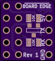
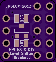
To do all that fun design, you probably want to breadboard your PIC and sensors. Unfortunately, the Raspberry Pi does not breadboard well (or at all). I created a little board to help me out, and now it might help you! This fits right on top of the RasPi GPIO header, uses the 5V and 3.3V supplies to shift the levels of the UART signals, and can even have the 5V and GND outputs used to power the rest of your circuit (though if it draws a lot of power, I'd recommend a separate supply and a common ground).
You saw the renders for the design in the beginning of the article; you can buy the boards from OSH Park. Buy the rest of the components from Digikey: the transistor is BSS138CT-ND, the resistors are RMCF0805JT10K0CT-ND. I used a 13x2 (100mil pitch) female header to fit into all of the RasPi headers, though you might prefer to just use a 6x2 female header. Finally, I used a 1x4 (100mil pitch) female header for the output, though again, you can do whatever you want - even solder wires directly on. The board edge is marked on the front silkscreen.
If you wanted to extend this design, you could do the same level shifting for most of the other I/O pins the Raspberry Pi provides. I only did the ones related to the UART signalling, but you may want to use others.
Coming up soon: a step-by-step guide to using Minicom on your RasPi (preferably using Raspbian) to talk to your PIC over UART.
Ches Koblents
March 25, 2014
March 25, 2014