Canon T3 Remote Control Design
This should work for all the Rebel series. I only have the T3/1100D.
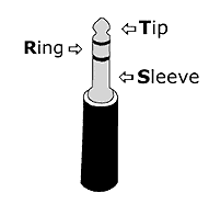
The good news is that remote control is drastically simpler than you would expect. The camera takes a 2.5mm audio jack. The tip of the jack is the release shutter, the middle band is the autofocus, and the base band (the sleeve; the band closest to the jack body) is common.


The two functions are activated when they're shorted to common.
I will want to control the camera in several ways:
- Pushbuttons to focus and release shutter
- A microcontroller with programmable modes
- External sources
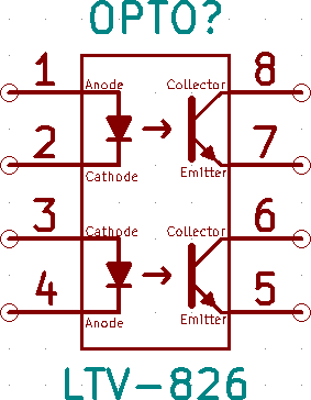
There are countless ways to build this system. However, for the sake of camera safety, I will use an opto-isolater / opto-coupler. Here's an example for what that looks like:


When the input pin goes high, an LED turns on, and a phototransistor on the other side of the chip turns on, shorting an output pin to common (ground). This prevents spikes, surges, and other various bad things from happening, because the camera control is electrically isolated! (Of course, you need resistors in series with the LEDs!)
The result: output pins never drive a voltage; they are either floating, or shorted to ground. Pretty good. It's not important to use TVS diodes in this application, as far as I can tell, but I may as well. More protection is good.
Here are the design requirements for control:
- Must allow pushbuttons to autofocus, and to fire the shutter
- Must allow a microcontroller to autofocus, and to fire the shutter
- Must allow external sources to autofocus, and to fire the shutter
- Must be powerable by USB
- Must have recheargable battery on-board, good for at least a week of active use
- Must indicate USB power status (on/off)
- Does not need to indicate activity - sounds from camera should be enough
- IC must break out signals externally
- IC must be easily programmable
- Must extend standard 2.5mm interface to camera
- Must enable common remote control modes
To go over the requirements one by one:
Must allow pushbuttons to autofocus, and to fire the shutter
Pushbuttons can either be active or passive elements here. As active elements, they would power pins of the optocoupler input. As passive elements, they would short autofocus and shutter release lines to the common line. As active elements, they use power; as passive elements, they do not. As passive elements, they do nothing that needs to be isolated. Therefore, I will place them near the 2.5mm output.
Must allow a microcontroller to autofocus, and to fire the shutter
This means a microcontroller should be included, as well as power sources. The microcontroller will momentarily turn the AF or Shutter pins high, then low again, to activate the corresponding camera controls. To save on power, experimental results will determine what resistor works well but lets little power be supplied by the MCU (microcontroller). Experimental results will also be needed to determine how long to set the pins high.
In addition, the MCU should be fairly basic and cheap, but big enough to store the code for various modes. I am currently thinking of using a PIC. I like working with PICs, and there are cheap and have various functions I may want.
Must allow external sources to autofocus, and to fire the shutter
There are two kinds of external sources: active and passive. Passive sources will create a short, and expect the controller to connect the short to the camera. Active sources will raise a pin high, and and expect the controller to short the appropriate camera connection. Unfortunately, breaking the passive contract - that is, an active source connected to passive pins - may be catastrophic to the camera. Instead of creating protective circuitry, I will not allow passive external sources, meaning I will simply not have any I/Os between the optocoupler and the 2.5mm jack. This will make debug slightly harder, but it will make the application of voltage much harder to do by accident.
An external active source will supply a signal to the board. The signal will be buffered to the appropriate voltage level, then passed to the optocoupler.
Must be powerable by USB
USB will charge the battery using a battery charging IC and supporting circuitry.
Must have recheargable battery on-board, good for at least a week of active use
This means a decent-size battery (chose LIR2450 - 100mAh nominal). It also means a good programming model, using interrupts whenever possible.
I also hope to have under 15mA active load, with less than one millisecond per second active operation, and under 100uA average load at 5V (500uW average power draw). A 100mAh nominal battery at 3.6V has a 360mWh capacity. The 5V boost converter should have a worst-case 70%-efficiency, giving a 250mWh available power. This translates to roughly 500 hours active use, or 20 days. Assuming an absolutely worst case of the battery dropping out after only halfway depleted, I still get 10 days active use, well above this requirement.
Whether this actually works as planned will be a whole different story, but the math shows that this is possible.
Math that takes into account all sorts of power draw figures from the components puts passive load around 50uA, active load around 10mA for less than 100us, which adds a negligible average power use of 1uA; this ends up burning just around 250uW, and gives 20 days active use. User-active mode, where the user is pressing buttons and expects some form of feedback, look more like 25mA for about 100ms, which brings average power use up to 2.5mA or 12.5mW, leading to a worst-case depletion in just 20 hours. Thankfully my heavy use scenario is five seconds of fiddling per minute, on average, which is still not great but acceptable.
Must indicate USB power status (on/off)
LED on the USB. 5V regulated output and a (usually) 2V forward voltage means a 1K resistor provides 3mA, more than enough to light up most small LEDs.
Does not need to indicate activity - sounds from camera should be enough
No LED should be powered by the battery for activity, as that is a waste of power.
MCU must break out signals externally
Active signals going to the optocoupler should be broken out. In addition, any configured communication protocol (such as I2C, SPI, or UART) should be broken out as well.
MCU must be easily programmable
This means two things to me. First, it means the programming interface should be properly broken out. Second, it means that a user should be able to cycle between modes, and select options, relatively easily. This means that there should be some sort of on-board user interface.
My current plans for the user interface are: four output LEDs, eight switches, a button (likely start/stop, though that functionality may be taken over by a power switch), and a mode selection button.
Must extend standard 2.5mm interface to camera
This means either a pre-soldered 2.5mm jack-terminated wire, or just a 2.5mm female slot that a male-male wire plugs into. The latter is far more elegant.
- - - - - -
Choosing an octo-coupler
Simple - works on a normal voltage (like 5V) with a resistor, has two channels, 8-pin package preferable, is cheap.
Choosing an MCU
I like to use PICs. I want some form of simple communication, plus all my I/Os. I can use I2C, UART, or SPI. To count the I/Os: two outputs for camera, four outputs for LEDs, two input buttons,eight inputs from dip switches. I looked at my choices and decided to upgrade - going for the PIC18F24K50 instead of my usual PIC16F722. It's a bit more expensive ($3) but allows USB. Quite nice.
Choosing a battery
I wanted a rechargable 5V coin cell but couldn't find one. Settled on the 3.6V LIR2450.
Sockets
MCU and optocoupler will be socketed. Adds to the cost, but great if I mess up.
LEDs
One for USB power, one to indicate battery charge status, four for MCU programming status. Let's go with SMD1206 here.
USB plug
Micro-B. Why not? It's easier to work with USB-A but micro-B cables are the most common by far. It's small.
Also, I'll add a TVS diode to D- and D+ lines. And since I'm going TVS, may as well add one to the 2.5mm jack, even though there's probably no need. Definitely costs nothing to add it to the PCB and decide later.
External signal amplification
Buffer / level shifter. Input a reasonable range, output 5V.
- - - - - -
The components in short:
- I/O
- 2.5mm plug for camera control. Tip is shutter, middle is AF, base is common.
- External signal in to control camera
- Camera control signal out
- Programming interface
- USB
- UART
- MCU
- PIC18F24K50
- Optocoupler
- Isolate camera from any electrical signals. Passive only! (Shorting tip to base, middle to base)
- Two channels: AF (middle to base), shutter (tip to base)
- Passive button to short manually
- User control
- Two buttons to AF, shoot manually
- One switch for bulb mode
- One button to turn operation on and off
- One button to switch modes
- 8 switches (256 values)
- Indicators
- Four LEDs to notify which mode and settings are being used
- One USB power LED
- One charge status LED
- Power
- USB, Battery; USB charges battery
- USB power passes through charge IC
- Battery output gets boost converted to 5V
Ches Koblents
October 3, 2013
October 3, 2013