
Canon T3 (2.5mm) Remote Control Board v1
As mentioned in my previous article, a Canon remote control only needs a 2.5mm TRS audio jack, and only needs to short tip-to-sleeve to shoot and ring-to-sleeve to focus. I took this knowledge and built a simple circuit: A pushbutton to focus, a pushbutton to shoot, and a switch for bulb mode (the switch activates the shutter just like the shutter button, but you don't have to hold it yourself.) I've included an optional TVS diode, which you may feel free to ignore. Here's the circuit:
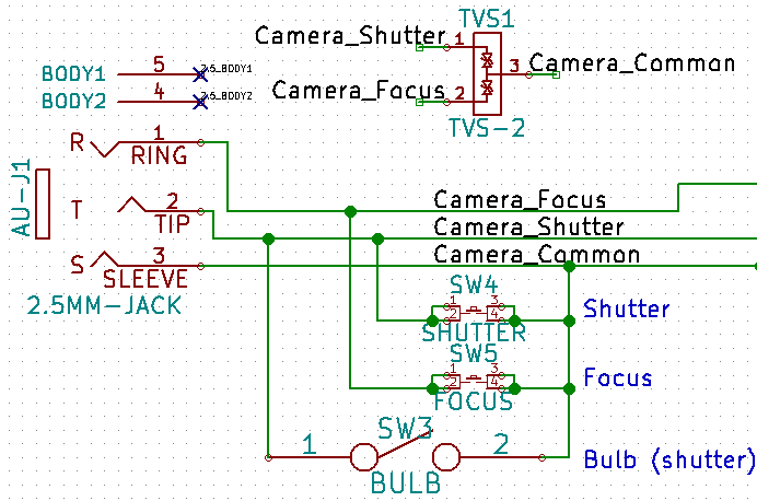
A transient voltage suppression diode protects against ESD, or tries to. I wasn't entirely sure what the proper specifications were on my remote control, so I picked one that looked reasonable. Feel free to ignore it.
But if I want a remote control, I want one that's automated, not one I always have to press myself. The manual function isn't going to disappear, but more fun stuff gets added. To give an advance summary, the board is going to get USB, serial, signalling I/O with buffers, a battery with a charger IC and a boost converter/regulator, a microcontroller, user input, user output, and even redundancy.
Before adding anything, though, it's important to remember that we're not sending any active signals, therefore the entire jack-and-buttons assembly should be electrically isolated from anything else we make. I made a common plane on the top and bottom of the PCB (common is essentially camera ground).
Next, an optoisolator / optocoupler (synonyms). It's an awesome bit of tech that transmits a signal by lighting up an LED, then catching the light with a phototransistor; all of this is done in the IC/package. Here's a diagram of the part I chose:
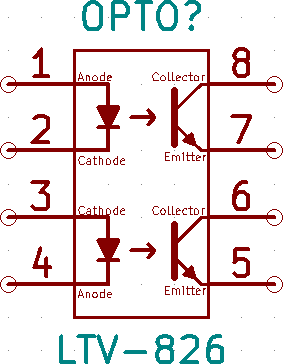
Two channels (focus and shutter); eight pins. Here's how I wired it: (note the resistors, since we're driving LEDs inside the isolator!)

Awesome. Now I can send logic level signals (I like 5V, but nothing stops you from choosing 3.3, or 1.8, or even lower if you find the right optocoupler) and still be electrically isolated.
Now, what if the 2.5mm audio jack is the wrong size? What if I want to attach a different jack, or a different method of control? That means I should have a way to break out signals. And, heck, let's accept signals too. But if we do that, we should make sure that our microcontroller can't be blown by shorting its output to ground or a positive supply. Therefore, let's do a pinout with a buffer on the signal lines, for both input and output:
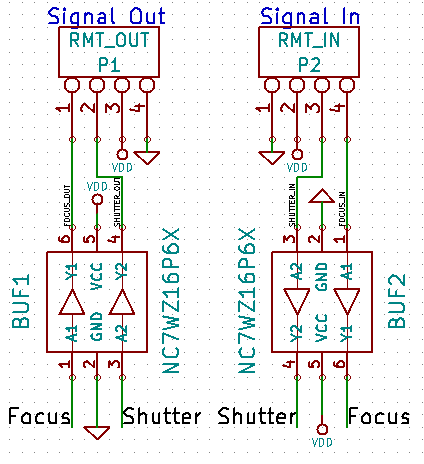
Great. Now we can accept signals, break signals out, and control the camera, all while isolating signals in, signals out, the main board, and the camera. But we're still not ready to pick the MCU. First, we have to figure out how to power the board.
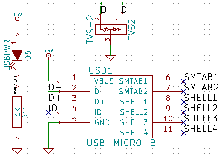
I chose to power my board with USB, because it's super easy and allows communication to the MCU. But I can't rely on USB, so I need a battery as well. I chose the LIR2450 based on some reference designs; I've written about that in the LIR2450 article. So let's put down the USB, with a TVS diode on its D+ and D- lines (this isn't optional here, but more or less required). I added a USB indicator light.
I added a battery charger IC based on a reference design from my LIR2450 article. Charge rate limited to around 50mA (rule of thumb: take nominal capacity of Lithium battery, cut it in half, and that's your max charge rate, giving a charge time of about two hours) with a 20K programming resistor. 4.7uF caps on both supply and output lines are required. Finally, a charge status LED is nice to have.
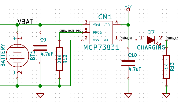
I found the battery online. The reference design matches the battery dimensions. I did probably put the charger IC slightly too far from the battery, and its layout is definitely sub-optimal (no power islands). Here's how the layout looks:
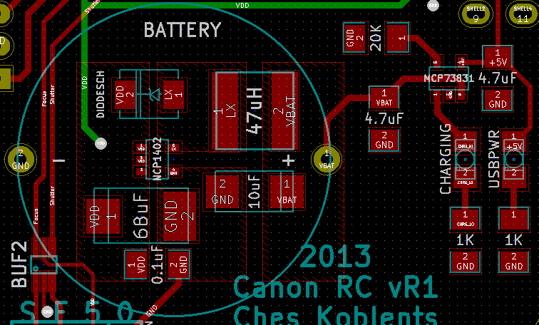
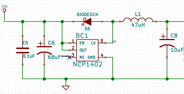
The stuff underneath the battery is a 5V boost converter and regulator. I realized I wanted 5V logic for interfacing with the outside world, so I used the above reference designs for that as well. Here's the schematic:
Now I have a camera control, in-out breakouts, USB, battery charger, battery, and 5V boost regulator. All that's missing is the MCU. I like PICs, and I wanted one that was USB-native. Before choosing an IC, I thought about my user inputs and status outputs:
- Eight general purpose switches
- One general purpose button
- One button to control program mode
- Four status LEDs
I actually had more requirements, picked a chip, laid everything out, and discarded some requirements. Therefore, the chip I picked - PIC18F24K50 - is bigger than I need it. I decided to keep it for this revision. This is also an excuse for me to buy the PicKit 3, because I don't think the PicKit 2 supports that chip. (I currently have neither.) Here's the diagram, and how I wired it with a minimal circuit (bypass caps on VDD-VSS pairs, and a special bypass cap on VUSB3v3):
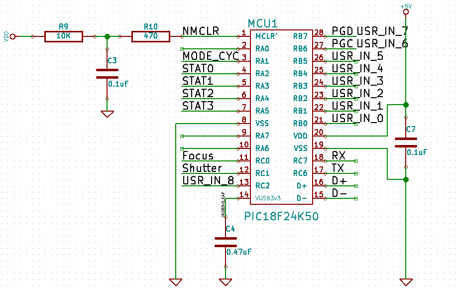
Note the switch on the MCLR bypass capacitor. It's said in the documentation that the cap should be present during operation, but not during programming. I suspect it'll be OK during programming, but I have a switch for this revision.
Finally, I added two redundant things. First, I added a jumper and a solder point to tie +5V directly to VDD, in case my charger-battery-regulator assembly didn't work. I can then run things directly off USB power. Second, I added another microcontroller - the PIC12F615, with which I am more comfortable, in case I messed up the PIC18F24K50. To make that work, I added two power switches to turn on/off the MCUs (and hopefully I don't mess up and turn both on...)
My boards came in, but I haven't finished assembly yet, so I don't know if it works. I'll write another entry when I find out. But first, here are some odds and ends:
- I chose large SMDs for resistors, LEDs, and so on, but through-hole for the chips. I'll downsize... eventually, once I get better at hand-soldering. Most SMDs are 1206, and I'll figure out how small I can go and still be comfortable hand-soldering. I'm sure I'll move to 0805, but hopefully 0603 is doable (Imperial codes). Similarly, the MCU will go to SOIC first, and later SSOP.
- In that vein, I do have a couple very small parts. We'll see how that works out.
- Both PICs and the optocoupler are socketed for now. Obviously that will go away if they go surface mount, but even if they don't, I'll still get rid of sockets for BOM purposes.
- The board was too big to fit into a 5x5cm square, so I paid ~$25 for 5 boards. This is very high. After some revisions, it'll cost a maximum of ~$15 for 10 boards instead.
- KiCAD correctly generated played slots for USB mounting holes, but gerbv did not display them properly. To take out the confusion, I switched to normal holes for future designs.
- Future revisions will get rid of the redundancy.
- Future revisions will get the battery charger IC closer to the battery, or under it.
- Future revisions will choose a slightly smaller MCU.
- Future revisions may have a better interface than eight switches and four LEDs, which will accept/display data essentially in binary.
- Future revisions will have parts on both sides.
- Future revisions will have a standard mount and a real-time clock.
- An e-ink screen would be nice too.
- If this is a complete failure, I'll shelve the project for a year.
This will most likely apply to any Canon dSLR that has a 2.5mm audio jack port for a remote control. Maybe not just dSLRs, maybe not just Canon. I can only talk about what I have.
My cost for a single prototype is $50 or so. I would like to see that reduced to $25 for a single prototype and $12/board for a small run of ten boards.
Disclaimer: If you break your camera from this article, not my fault. I have no idea what I'm doing. I'm not responsible for equipment damage. I'm not responsible if you do something unsafe and electrocute yourself. Don't stick wires into wall outlets and lick them. Don't use a metal axe to try to steal copper out of 300KV transformers. You get the point.
Ches Koblents
October 13, 2013
October 13, 2013